Monday 31 December 2018

Milestone 1 Complete

This is an update on the self driving car project. Milestone 1 has been completed.

Parts:
1 - Raspberry Pi Camera V2
2 - DF055B Servo with Pan Bracket
3 - USB Micro Battery Bank
4 - Raspberry Pi 3 Model B
5 - L289n Motor Driver
6 - 6xAA Battery Pack
7 - Arduino Nano
8 - 4xAA Battery Pack

4 Wheel Car kit Chassis from some Chinese distributor
(cheap but gets the job done, soon I will upgrade to an RC car with better motors, chassis and steering)

Power
At the moment I am using separate power supplies to avoid any additional power circuitry for now.
The 6xAA Battery Pack provides the 9V to the 4 motors
The 4xAA Battery Pack provides 6V to the servo motor
Finally the USB Micro Battery Bank is used for the raspberry pi.

Control
The Raspberry Pi is the main brain of the whole system which is running the control scripts to control everything and to interface with a controller.
The arduino nano is dedicated to servo control (due to real time PWM) which is controlled via serial commands from the Pi.
The controller is connected via bluetooth directly to the Pi.

Stream
Camera feed is streamed using netcat and named pipes. Essentially netcat is a udp/tcp transport program which encoded H.264 is sent over to the PC from the raspberry pi and then decoded on the PC. This allows for the use of Open CV and further machine learning on my GPU since the Pi doesn't have enough processing power. Even though there is latency due to streaming, this is still faster than allowing the Pi to process everything.

Self Driving Cars

With the rise in popularity of self driving cars due to companies such as Tesla and Waymo, we have made significant progress into making it more applicable in society.

Image result for waymo
Waymo car: Source

My next project will be creating a miniature self driving car where I will be exploring the basic problems of lane detection, stop sign detection and object detection.

Although these problems have already been solved, I intend to use this as a learning experience to learn about these existing solutions and perhaps add my own spin on things as I learn more about the subject.

I've broken up this project into several milestones to make the problem a bit easier to solve.

Here is my current rough plan:

Milestone 1:
- Make a remote controlled car using ps3 controller
- Be able to control camera and steering
- Stream image data to pc

Milestone 2:
- Basic open cv recognition (stop signs)
- Neural network on pc using CUDA (stream data from rc car)
- Make car stop at stop sign

Milestone 3:
- Lane detection
- Traffic lights

Milestone 4:
- Object tracking and following

Milestone 5:
- Upgrade to RC buggy car 
- Battery upgrade

Milestone 6:
- Finalize and make working

To make a self driving car using raspberry pi camera module and opencv
-Be able to stop at a stop sign for 3 seconds then go
-Be able to follow a traffic light
-Be able to navigate lanes
-Bonus goal - follow an object around

Monday 8 October 2018

Finished Electronics

In this post, I will be showcasing the finished electronic product for the WH40k themed pedometer. The PCB was designed using Ki Cad and was fabricated by PCBway in China.

PCB without the screen

All of the component were hand soldered by me. However I ran into quite a bit of an issue with the smaller chips especially the 14 LGA package of the accelerometer. Knowing that most surface mount component footprints were created to be used in a re-flow oven or soldered by machine, I purposely chose slightly wider footprints to cater for hand soldering (can especially be seen with the crystal). 

Not knowing the real size of the LGA footprint, it came out as impossible to solder using a soldering iron. Luckily for me, my university had a hot air soldering station which I could use. After a few burnt out chips and burnt fingers, I managed to finally solder the accelerometer and to my surprise, it worked even though I might have heated it up too long.

With the screen

The final product looks a bit messy and I probably could've made it more compact, but then again that would've been a pain to hand solder.

The current image displayed is the main menu of the pedometer and the little marine pops up in random locations over the screen.

I still have a lot of work to do with regards to the software and looking at it now, using an atmega328p might've restricted me in terms of computational power quite a lot. On the plus side, its forcing me to write super efficient code which might be useful in the future.

I'm also considering adding a 3d printed case in the future but I first have to learn how to use some sort of autoCAD software.

Sunday 15 July 2018

WH40k Digivice: Standalone Atmega328p

Atmega328p with avrdude

In this post, I will outline how to get a working standalone atmega328p. This can be done using avrdude which is an in system programmer for avr chips.

Requirements

  • Arduino and its IDE (i use the uno) - this will be used as an ISP programmer
  • A computer with USB type A to USB type B cable (the blue cable that usually comes with arduinos)
  • Jumper cables - a makeshift programming cable
  • A breadboard
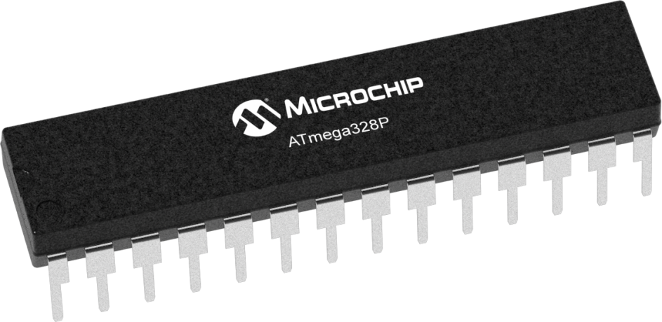
  • atmega328p microcontroller - the most important ingredient
  • 1k ohm resistor
  • Power - 3.3V or 5V depending on your clock speed, I will be using 3.3V
  • Crystal oscillator (optional) - select depending on your requirements, for my project I will be using a 16Mhz crystal (clocked down to 8Mhz)
  • If you are using an external crystal oscillator - 2 x 22pF ceramic capacitors
  • avrdude program - Download Link 
  • avr-gcc - included in the software above
  • make - for windows Link 
  • Your choice of IDE, I use sublime text 3 with command prompt

Procedure

First install all of the require software, mainly avr dude. Also make sure you have the Arduino IDE.


Check that avrdude is installed

After correctly installing, you should be able to type avrdude into your command prompt or terminal and this block of text should show up. Also check avr-gcc by typing that in as a command and also make, you should get something like the image above.

Next plug in your Arduino into your PC and select the appropriate COM port. This COM port will later be used in avrdude.

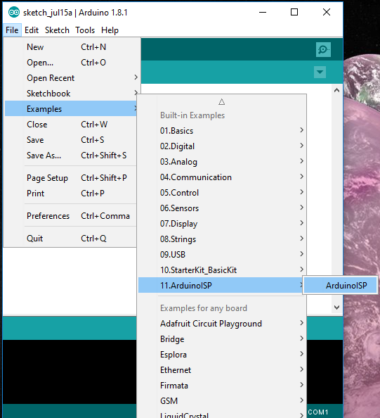
Now go to File->Examples->11.ArduinoISP->ArduinoISP and upload this code to your Arduino.

Arduino In System Programmer

This program allows you to use your Arduino as a in system programmer which is quite handy.

Once you have written a simple program in your IDE of choice, it is now time to upload the program onto the atmega. I might make a post about basic AVR-C in the future. If you don't have any code as of yet, download ledblink.c as a first program. 
Link to sample ledblink.c  - Credit to Howard Mao Blog, a great blog for embedded projects.

Also download this MakeFile making sure that all the files are in the same folder

Navigate to your folder location using the cd command. Usage: "cd C:\(Your file directory)"

For example my folder is located on C:\Users\opimu\desktop\project\, 
then i would type "cd C:\Users\opimu\desktop\project\" into the command prompt.

Now using your IDE, edit the makefile that has just been downloaded.


The text underlined in red is what you should change depending on your setup. If you are writing in c++ then avr-g++ is required in the CC= field. Otherwise use avr-gcc.

The F_CPU field determines your clock speed. The out of the box atmega328 is default at 1Mhz therefore 1E6 should be input there.

The COM port is dependent on your system which can usually be checked in the arduino IDE as shown below. It should be the same port you used to upload the ArduinoISP program. Tools -> Port


Where the PROJ_NAME= enter your program name. In the case of the example code, it should be PROJ_NAME=ledblink.

Once all those parameters are filled in correctly, simply type "make" in your command prompt and the code should compile as shown below.


If anything other than this comes up, there's probably an error somewhere either in the parameters mentioned above or file extension naming.

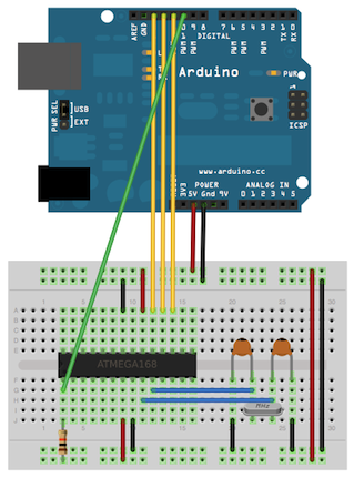
The next step is to wire up your atmega328 to your arduino using the jumper cables, crystal if needed etc
Wiring diagram: Source

Note, in this case we are using the arduino as a power supply, however alternatively, an external 3.3V or 5V battery source can be used. In my project I use a switch mode power supply or a boost converter which I will talk about in a later post.

Once you have wired up as show in the diagram above, simply type "make upload" to program your microcontroller. If the program was uploaded successfully, you should see the following text below. Otherwise check that all your connections are correct and that the atmega328p chip is receiving power.


To check that the program is working, put a 330 ohm resistor in series with an LED into PORTD 6 of the micro controller. (Check the atmel datasheet for location of pins)

That's all there is to it! Have fun using the standalone atmega328p chip which is much cheaper to buy on its own. A cheap linear regulator can also be used with a few batteries as a power supply.

My Current Chip Programming Setup

I've re purposed an old PCB that I made as part of a university course to be an easy programmer since I've designed it with a micro controller socket to easily remove the chip in case of faults and also a female pin connector with cable for easy plugging in of the programming cable.

My custom ISP programming cable


My old PCB from university, comes with a linear regulator and 9V battery socket


How i program my chips.
Note: Instead of wasting batteries, I plug my pcb into my lab bench power supply.

Saturday 9 June 2018

Project: Warhammer 40k themed digivice

Welcome to my first ever project on this blog. My goal is to build a warhammer themed digivice reminiscent of my childhood days. Throughout the development of this project, I will be posting updates with small tutorials on how I've implemented specific functions of the device.

What is a digivice?

Digivices were these cool toys which tracked your steps using a pendulum type pedometer which used to make a clicking sound with each step you took. These steps would then be counted allowing you to "progress" through areas of a map, and subsequently battle different digital monsters (Digimon) and eventually fight the boss. 

I thought these were an effective way to get kids to exercise back in the day and also get outside of the house into the great outdoors, which is what too many parents want their kids to do nowadays. However kids cheated the game anyway by shaking the digivice to simulate steps and thus progress faster in the game. Nonetheless, it was one of the toys which I enjoyed the most.

Image result for digivice
Digivice: Source

Outline of project

I intend to create my own version of the digivice but with a warhammer 40k theme, because warhammer 40k has the most bad ass lore out of every sci-fi universe I've ever seen. The story of WH:40K is basically 40,000 years in the future where multiple alien civilizations including the human race are fighting for dominance over the galaxy.

File:Warhammer-warhammer-40k-space-marines-black-templars-imperors-champion.jpg
Space marine from the WH40k universe: Source

The basic game play mechanics of my version of the digivice, will come along in a later blog post, but it will consist of conquering alien planets with the goal of retaining as many planets as possible.

Current Hardware List

I'll be using an atmega328p microcontroller as that is my most familiar microcontroller family (the same chip that's used on the arduino uno). However I'll be avoiding using Arduino libraries and go straight to avr-c so I can get down and dirty as close to the hardware as possible (so called bare metal programming).

I'll also be using a couple existing libraries to save time and modifying them to suit my needs.

product primary image
ATmega328p Micocontroller: Source

My screen of choice is the cheap and low power Nokia5110 LCD displays. Knowing they're made by Nokia, they're probably close to indestructible. These displays also interface quite nicely with the atmega328p with several libraries already out there. There is a slight issue with them which I'll detail in a later post.

Graphic LCD 84x48 - Nokia 5110
NOKIA5110 LCD Display: Source

I'm still yet to find a pedometer for my digivice but it will most likely be one of those cheap accelerometer modules.

As for power, a simple boost/buck converter will suffice given I will run this off a couple of AA or AAA batteries.

Equipment


The main thing i will most likely be using is the lab power supply. The oscilloscope will be useful for checking for correct clock rates for example, the main crystal oscillator and the SPI clock rate. I also have a PC with an arduino nano connected via usb, and which I will explain its use in the next blog post.

Forward

In the next blogpost, I will be describing the first step in the process which is to setup the atmega328p and flash the first program onto it. Look forward to it!

Welcome to my blog!

This blog serves as documentation for my projects.
EECS degree from UNSW with interest in embedded systems.