Tuesday 27 August 2019

Self Driving RC Car

In this post, I will outline how I got my RC car to drive by itself using deep learning. The RC car has a camera to see whats in front of it, for example a road that it can follow. Images from the camera are then used as input to a deep learning model which outputs a steering direction, such that the RC car will steer depending on what it sees, very much similar to how humans steer a car. This type of problem is called a computer vision problem which is a field primarily concerned with using visual data such as a video feed or images to perform tasks.

The task for the RC car is to follow the road. The road is made up of paper sheets laid down to form a track. I decided to use paper since I could create different tracks easily, rather than painting road lines.


What is deep learning?

The goal of machine learning is to enable machines to act on information. This is achieved by creating a model which takes some form of input data and gives an output. Deep learning models are a specific class of models based on the perceptron which will be used for this task. Before that a brief explanation of supervised learning is required.

Supervised learning

To introduce deep learning, I will start off by talking about supervised learning. Supervised learning is when we provide the output we want the model to give, along with the input that is generated by it. As a result, the model will be only as good as the data we provide to it.

Perceptron

A perceptron aims to mimic a neuron in the brain as it has some inputs and provides a single output. Neurons take in electrical impulses as input and then in turn output another electrical signal.

The perceptron has parameters which describe it and these parameters can be learnt by using the data. This is the process of training. These parameters are adjusted depending on if the output is correct or not, correct meaning it it the same as the provided output. If an output is incorrect then we would like to adjust the parameters so that the model will output the correct value.


Perceptron Model

Multi layer perceptron

The issue with just normal perceptrons is that it is unable to model complex tasks, by stacking many of them together, we can get them to model more interesting problems.

Training the model

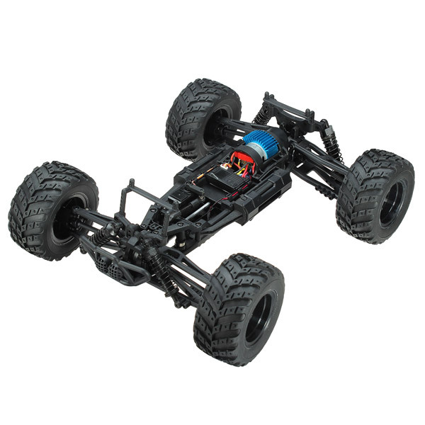
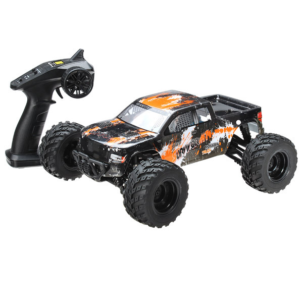
Previously, I had introduced a ps3 controlled RC car and is the main system used for training. Training data is collected by manually controlling the car and collecting images along with steering angle. The steering angle is tied to how much the analog sticks are moved.

The training data is then given to the deep learning model to adjust its parameters. A basic method to perform this is called gradient descent.

Control

After the model has been trained, the RC car will stream images to the computer. The computer then processes these images using the model, and output a steering angle. This was done to utilize the GPU of the computer which is able to train and use deep learning much more quickly than the CPU of the raspberry pi. The computer then sends the steering angle back to the RC car such that it can steer itself.

Improvements

One main problem with this method is that it requires a good connection between the RC car and the computer to send large amounts of image data. Ideally, it should be processed locally on the raspberry pi, however the raspberry pi is too slow for that sort of data processing. Alternatively a more powerful system could be used such as Nvidia's Jetson.

Nvidia Jetson

Different deep learning architectures could also be considered in the future. In particular, a flavor of deep learning called the convolutional neural network is designed especially for image data.

Finally more data usually works better for deep learning models as it helps with a problem called over-fitting. This occurs when the model is trained too much on the training data and is unable to generalize to other new data it has not seen before.


Tuesday 2 July 2019

RC Car PS3 Control Demo

Here's a little video demonstration of the new RC Car working!


Stay tuned for the next blog post on update milestones and progress on autonomy!

Modifications to the RC Car

Here are the list of modifications made to get the RC car ready for autonomous driving.

Replaced ESC

First of all, the electronic speed controller (ESC) is used to take control signals such as from a remote control and convert that to a signal that can control the motor's speed and direction. The plan was to figure out where and what types of signals that the ESC took as input, so that I could replicate them using a micro-controller such as an Arduino. This turned out to be a fruitless approach since the ESC was coated in a waterproof plastic that prevented access to the electronics. This led me to decide to purchase my own ESC that could be able to take in simple input to control the motor.

HobbyKing X-Car 45A Brushed Car ESC
HobbyKing X-Car 45A Car ESC: Source

If you recall from the last post, the motor in the RC car is rated at 40A, which led me to buy the ESC with the closest current rating as possible. This was a nice and simple speed controller to work with, and all that I had to do was de-solder the old from the motor and replace it with this one.

The inputs to the ESC were also simple as it uses PWM to control the motor speed and direction. When you turn on the ESC, it will record the current PWM signal being sent to the motor as the stationary position. Thus a signal with a higher duty cycle will signal the motor to spin forward and faster as the duty cycle increases. On the other hand, a signal with a lower duty cycle will cause the motor to spin backwards and at a faster rate as duty cycle decreases. This was simple to implement using an Arduino with its inbuilt PWM function.

Steering servo modification

The inbuilt steering servo on the RC car was unfortunately of the analog type. Analog type servos have a potentiometer output where the resistance corresponds to the current angle of the motor. This meant that an external PID controller had to be used to control the steering.

PID Controller from old servo

Fortunately, I had an old servo motor lying around which somehow had very close potentiometer resistance to this steering servo. The old servo is a digital type and contains its own PID controller. It was as simple as de-soldering the PID controller and attaching it to the steering servo. From there I was able to control the steering angle using PWM. A little experimentation was required to see what duty cycle corresponded to which angle.

Speed Restriction

Since the RC car was capable of doing up to 33km/h, this was overkill for my application. To restrict the speed of the motor, I experimented with different PWM duty cycles and gauged by eye, an adequate speed for the autonomous navigation. On the Arduino, this speed was set as a fixed speed, and now the RC car is only capable of driving at the decided speed.

Mounting Structure

The bare chassis of the car has no nice place to mount the electronics such as the raspberry pi and the Arduino. As a result, I had to build my own mounting structure. I had some pieces of medium density fibreboard (MDF) lying around and seemed suitable for the mount. With that, I reused one of the pieces from the old robot car kit since it was a nice mount with holes to tie things to.

Bare Chassis

The resulting new chassis allowed me to mount all the items needed for autonomous navigation. I used zip ties and blu-tac to secure all the items.

Everything mounted sort of nicely.
You can see the old plastic mount from the old kit used on top.

Another view of the mount

Battery Upgrades

The batteries that were provided with the car were two 18650 cells in series with only 1500mAh capacity. This was clearly not enough for a longer drive and to also power the on-board electronics. I decided to upgrade to a 5000mAh battery cell with 7.4V 2S output. Besides the added capacity, this battery also had a much higher discharge rate if needed in the case of more power required for the motors.
Turnigy 5000mAh 2S 20C Lipo Pack w/XT-90
5000mAh 2S Battery: Source

To power the electronics, I decided to use a 5V USB powerbank which had a 6600mAh capacity.

Closeup of the power bank

Putting everything together

All the components

Parts list:
  1. ESC Controller
  2. Arduino
  3. Raspberry pi and camera
  4. RC 390 DC Motor
  5. Batter Bank
  6. Steering Servo
The blue prism sitting underneath the plastic mounting plate is the LiPo battery mentioned before.
This new RC car uses the same method of control as the old RC. However, instead of a dedicated motor driver, an ESC and an Arduino is used to control the motor, and steering is also controlled by the Arduino.

The raspberry pi takes in commands over Bluetooth from the PS3 controller, which then get translated into a serial command output to the Arduino. The Arduino then parses this command and determines where to steer and how much to accelerate etc. It was simple to map one joystick to the steering and the other joystick to the motor control.

This will most likely be the final vehicle for autonomous navigation with the current milestones.

New RC Car

I decided to replace the old robot car that was built using a cheap kit, with a more powerful RC car. The biggest differences are the steering mechanism and motor power.

Steering Mechanism Difference

The original robot car used what was called differential steering, in that to turn in a direction, the opposite wheel would spin faster compared to the wheel on the same side. To illustrate with an example, to turn left, the right wheel would spin faster while the left wheel spins slower, causing the car to rotate to the left.


Image result for differential steering
Mechanics of differential steering: Source

However the problem with this was that the wheels would cause the car to slip on a difficult to grip surface such as a timber floor. This was seen in my earlier video demonstration where the car would occasionally slip while turning (Link to video). This led me to decide to use a different steering mechanism.

The new RC car that I am currently using, utilized what's called Ackermann steering. This uses a steering linkage that orients each wheel appropriately. The main property of this steering mechanism is that the wheels are oriented at slightly different angles to compensate for the different circle radii that are being traced during turning. This prevents the wheels from slipping whilst turning for the cost of being more complex.


Image result for ackermann steering
Different angles of the wheels: Source
The reason I have decided to go with Ackermann steering, is that I can specify turning angles rather than trying to figure out the speeds of each side for differential steering. This will make it much easier to control.

Motor Power

The other significant difference is the motor power. The cheap robot car kit uses these small DC motors which are powered by a higher voltage but a lower current. These are typically powered by combining several AA batteries in series to operate in the voltage range 9-12V. Then gears are used to convert the high rotation to more torque. Even then, the power or torque of these motors are severely limited by the battery current output (1A maximum for AA batteries) and also the thickness and number of coils that the motor has.

Cheap DC Motor

The new RC Car has a motor that is rated for up to 40A. This motor has much more torque and runs off 7.4V which is two LiPo cells in series. The car has an advertised maximum speed of 33km/h but for our purposes, this is overkill and a speed limiter will be implemented.


Image result for rc 390 dc motor
RC 390 DC Motor


The RC car

Without further ado, here's the new car that I will be using. It is a RC 4WD 1:12th Off Road Truck. The main reason I picked this was that it was on sale for half price! It seemed to do the job and has the much needed Ackermann steering. Another reason was the size of it meant it would be able to hold the components needed for autonomous driving. Link to car


The car without the cover
However, in its out of box state, it doesn't have enough battery power, no place to easily mount components and also the steering and the motor cannot yet be controlled with a micro-controller. Many modifications are required and this will be detailed in the next post!

Wednesday 22 May 2019

Digit Recognizer

This is an application that allows a user to draw a digit onto a canvas and the program will try to predict what the user had drawn. It uses neural networks to classify and is trained on the MNIST data set which contains handwritten digits ranging from 0-9. As of such, this program is only able to classify digits from 0-9.

The link to the github repo is here


Neural network models

Different neural network architectures were used to compare their performance. The list below describes the different models used and the nodes in each layer.
  1. Input 784 - Hidden 50 - Output 10 using only numpy
  2. Input 784 - Hidden 800 - Output 10 using tensorflow
  3. Input 784 - Hidden 800 - Hidden 800 - Output 10 using tensorflow
  4. Input 784 - Conv 32 5x5 filters with max pooling - Conv 64 5x5 filters with max pooling - Fully connected 1024 - Output 10

Model number 1 has an accuracy on the test data of 90%. Model number 2 had an improved accuracy of 95% and Model number 3 only had small improvements of 96%. Finally model number 4 performed the best with 98% accuracy.

Model number 4 was subsequently chosen as the classifier for the digit recognizer application.

Purpose of the project

I made this application as an attempt to understand neural networks better. This prompted me to make a neural network using only matrix multiplications in numpy which allowed me to more deeply understand the calculations required to perform classification with these models.

After I had made a simple neural network, I noticed I was restricted to a small architecture of neural networks, that is having few layers and few nodes in those layers. This was because everything was being calculated on the CPU.

As a result, I decided to implement neural networks using Tensorflow which utilized my GPU to perform calculations in parallel, thus significantly improving speed. This then allowed me to explore deeper structures and also computationally expensive architectures in particular the convolutional neural network (CNN).


Image result for gtx 1060
This is the GPU that I currently have.

Modules used

Python 3
tKinter -  for the GUI and canvas drawing application
Pillow - for saving the image and performing preprocessing such as filtering
numpy - for the arrays
tensorflow - fast calculation
pickle - to save weights after training
matplotlib - to visualize the dataset

Structure of the program

System Diagram

The canvas app talks to the neural network model to perform classification. By separating the canvas from the model, different models are able to be switched in easily. The neural network trainer then trains the specific neural network model by providing data in batches and performing optimization. After the neural network has been trained, the weights can be saved into a database. 

Things to be improved

The application struggles with some digits such as the digit number 9. Also if the user does not draw the digit "nicely" in the box provided, the results can widely vary.

To improve this, perhaps better data preprocessing is required such as stretching the digit to fill the canvas. However, I believe the biggest improvements would be to use a larger database of digits containing skewed and digits of different sizes to account for all the different possible variations.