Replaced ESC
First of all, the electronic speed controller (ESC) is used to take control signals such as from a remote control and convert that to a signal that can control the motor's speed and direction. The plan was to figure out where and what types of signals that the ESC took as input, so that I could replicate them using a micro-controller such as an Arduino. This turned out to be a fruitless approach since the ESC was coated in a waterproof plastic that prevented access to the electronics. This led me to decide to purchase my own ESC that could be able to take in simple input to control the motor.
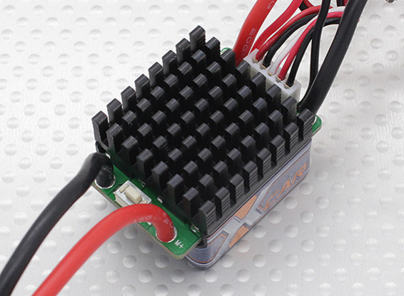 |
| HobbyKing X-Car 45A Car ESC: Source |
If you recall from the last post, the motor in the RC car is rated at 40A, which led me to buy the ESC with the closest current rating as possible. This was a nice and simple speed controller to work with, and all that I had to do was de-solder the old from the motor and replace it with this one.
The inputs to the ESC were also simple as it uses PWM to control the motor speed and direction. When you turn on the ESC, it will record the current PWM signal being sent to the motor as the stationary position. Thus a signal with a higher duty cycle will signal the motor to spin forward and faster as the duty cycle increases. On the other hand, a signal with a lower duty cycle will cause the motor to spin backwards and at a faster rate as duty cycle decreases. This was simple to implement using an Arduino with its inbuilt PWM function.
Steering servo modification
The inbuilt steering servo on the RC car was unfortunately of the analog type. Analog type servos have a potentiometer output where the resistance corresponds to the current angle of the motor. This meant that an external PID controller had to be used to control the steering.
 |
| PID Controller from old servo |
Fortunately, I had an old servo motor lying around which somehow had very close potentiometer resistance to this steering servo. The old servo is a digital type and contains its own PID controller. It was as simple as de-soldering the PID controller and attaching it to the steering servo. From there I was able to control the steering angle using PWM. A little experimentation was required to see what duty cycle corresponded to which angle.
Speed Restriction
Since the RC car was capable of doing up to 33km/h, this was overkill for my application. To restrict the speed of the motor, I experimented with different PWM duty cycles and gauged by eye, an adequate speed for the autonomous navigation. On the Arduino, this speed was set as a fixed speed, and now the RC car is only capable of driving at the decided speed.
Mounting Structure
The bare chassis of the car has no nice place to mount the electronics such as the raspberry pi and the Arduino. As a result, I had to build my own mounting structure. I had some pieces of medium density fibreboard (MDF) lying around and seemed suitable for the mount. With that, I reused one of the pieces from the old robot car kit since it was a nice mount with holes to tie things to.
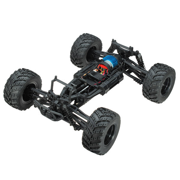 |
| Bare Chassis |
The resulting new chassis allowed me to mount all the items needed for autonomous navigation. I used zip ties and blu-tac to secure all the items.
 |
| Everything mounted sort of nicely. |
You can see the old plastic mount from the old kit used on top.
 |
| Another view of the mount |
Battery Upgrades
The batteries that were provided with the car were two 18650 cells in series with only 1500mAh capacity. This was clearly not enough for a longer drive and to also power the on-board electronics. I decided to upgrade to a 5000mAh battery cell with 7.4V 2S output. Besides the added capacity, this battery also had a much higher discharge rate if needed in the case of more power required for the motors.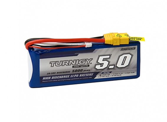 |
| 5000mAh 2S Battery: Source |
To power the electronics, I decided to use a 5V USB powerbank which had a 6600mAh capacity.
 |
| Closeup of the power bank |
Putting everything together
 |
| All the components |
Parts list:
- ESC Controller
- Arduino
- Raspberry pi and camera
- RC 390 DC Motor
- Batter Bank
- Steering Servo
The blue prism sitting underneath the plastic mounting plate is the LiPo battery mentioned before.
This new RC car uses the same method of control as the old RC. However, instead of a dedicated motor driver, an ESC and an Arduino is used to control the motor, and steering is also controlled by the Arduino.
The raspberry pi takes in commands over Bluetooth from the PS3 controller, which then get translated into a serial command output to the Arduino. The Arduino then parses this command and determines where to steer and how much to accelerate etc. It was simple to map one joystick to the steering and the other joystick to the motor control.
This will most likely be the final vehicle for autonomous navigation with the current milestones.
No comments:
Post a Comment