I decided to replace the old robot car that was built using a cheap kit, with a more powerful RC car. The biggest differences are the steering mechanism and motor power.
Steering Mechanism Difference
The original robot car used what was called
differential steering, in that to turn in a direction, the opposite wheel would spin faster compared to the wheel on the same side. To illustrate with an example, to
turn left, the
right wheel would spin
faster while the
left wheel spins
slower, causing the car to rotate to the left.
 |
| Mechanics of differential steering: Source |
However the problem with this was that the wheels would cause the car to
slip on a difficult to grip surface such as a timber floor. This was seen in my earlier video demonstration where the car would occasionally
slip while turning (
Link to video). This led me to decide to use a different steering mechanism.
The new
RC car that I am currently using, utilized what's called
Ackermann steering. This uses a
steering linkage that orients each wheel appropriately. The main property of this steering mechanism is that the
wheels are oriented at slightly different angles to compensate for the different circle radii that are being
traced during
turning. This prevents the wheels from
slipping whilst turning for the cost of being more complex.
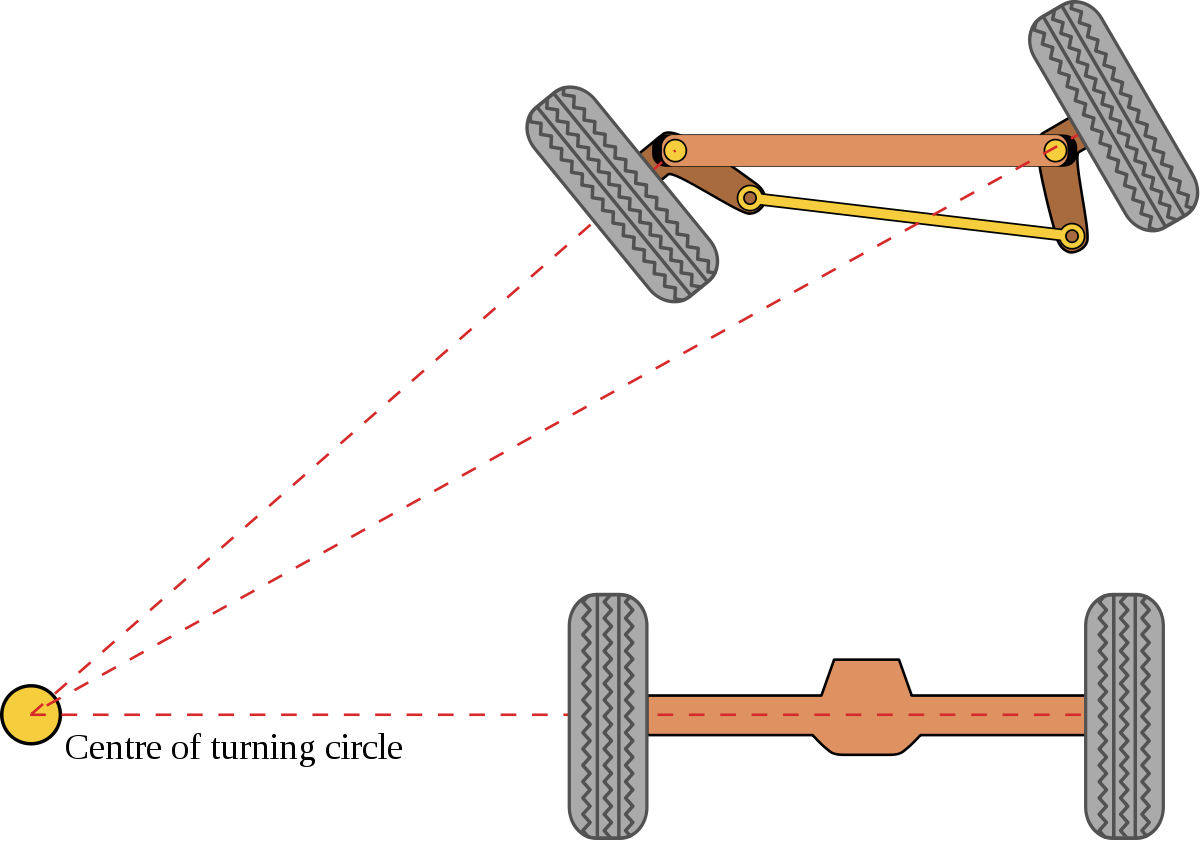 |
| Different angles of the wheels: Source |
The reason I have decided to go with
Ackermann steering, is that I can specify turning angles rather than trying to figure out the speeds of each side for
differential steering. This will make it much easier to control.
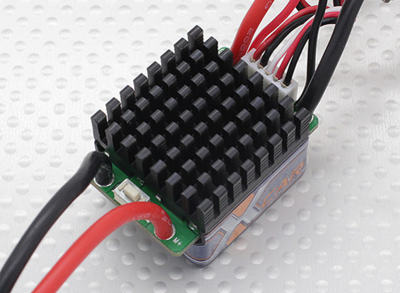
Motor Power
The other significant difference is the motor power. The cheap robot car kit uses these small DC motors which are powered by a higher voltage but a lower current. These are typically powered by combining several AA batteries in series to operate in the voltage range 9-12V. Then gears are used to convert the high rotation to more torque. Even then, the power or torque of these motors are severely limited by the battery current output (1A maximum for AA batteries) and also the thickness and number of coils that the motor has.
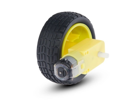 |
| Cheap DC Motor |
The new
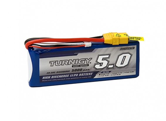
RC Car has a motor that is rated for up to
40A. This motor has
much more torque and runs off
7.4V which is two LiPo cells in series. The car has an advertised maximum speed of
33km/h but for our purposes, this is
overkill and a
speed limiter will be implemented.
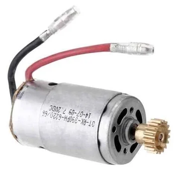 |
| RC 390 DC Motor |
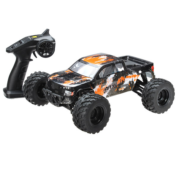
The RC car
Without further ado, here's the new car that I will be using. It is a
RC 4WD 1:12th Off Road Truck. The main reason I picked this was that it was on sale for
half price! It seemed to do the job and has the much needed
Ackermann steering. Another reason was the
size of it meant it would be able to
hold the
components needed for
autonomous driving.
Link to car
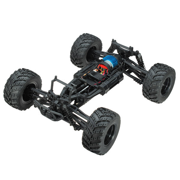 |
| The car without the cover |
However, in its
out of box state, it doesn't have enough
battery power, no place to easily
mount components and also the steering and the motor
cannot yet
be controlled with a
micro-controller. Many
modifications are required and this will be detailed in the
next post!